Water/Foam Monitor Mapping (Trajectory simulation)
FPEC's mapping software (Trajectory simulation) for water or foam monitor comprise flying trajectory calculation programs of water or foam stream discharged from a nozzle. The water or foam discharged stream will be affected strongly by wind, which effect can be calculated by this program.
In case of water discharge, the trajectory simulation is possible for not only solid stream but also for spray streams with up to 120 deg angle.
The calculated trajectory is displayed on the 3D graphics by AutoCAD to check if coverage by the monitor is adequate visually. By this mapping software (Trajectory simulation), appropriate mapping of fixed or portable monitors, fire trucks etc., can be studied under windy conditions,.
|
Experience the simulation
|
Water Monitor
Water stream trajectory depends on characteristic on the nozzle type. Based on a nozzle maker's data on discharge trajectory (at least two points are required), specific factors for this software will be decided and then the trajectory simulation will be dedicated for the nozzle.
As described below, this software is applicable for various types of water nozzle as well as water monitor, but not for flat type nozzle.
- Applicable nozzle type
- Variable nozzle
hand line nozzle, water monitor, water cannon on the fire truck, telescopic tower truck nozzle,etc., - Jet nozzle (solid stream nozzle)
hand line nozzle etc., - Water curtain nozzle
To discharge water jet straight up in the air to make water curtain by falling water - Spray nozzle
applicable for various types of the nozzle., and can simulate discharge pattern at any angle of discharge under any wind condition.
It is possible to check if there is a dry spot without actual water discharge test. - Sprinkler nozzle
It is possible to check if there is an area being not covered without actual water discharge test.
- Variable nozzle
- Discharge pattern
It is possible to simulate the trajectory for not only jet stream but also spray stream at any spray angle. - Effect by wind
As well as following wind or against wind, effect of any angle wind can be reflect the trajectory simulation. - Water discharge direction
It is possible to simulate the trajectory for water discharge in any angle direction. In case of water curtain nozzle, maximum height of the water curtain, which discharged water is able to reach, can be calculated. - Display
The trajectory is shown on plant layout or map on 3D AutoCAD drawing.
Example-1
|
Figure 1-1;various spray angle discharge from fixed water monitor
|
Figure 1-2;water discharge from upwind and down wind simultaneously
|
Example-2
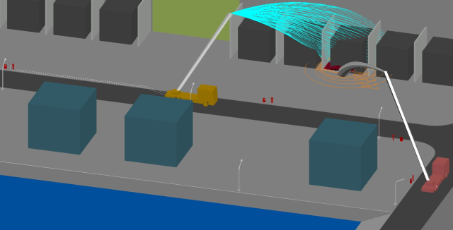
Figure 2-1 shows water discharge from telescopic tower nozzle (left side fire truck) and foam discharge (right side fire truck). The heat flux contour map is also shown around the transformer fire.
As shown in figure 2-2, various studies are possible for fire situations by using suitable layout drawing or pictures.
|
Figure 2-1;discharge water and foam to fire at transformer from fire trucks |
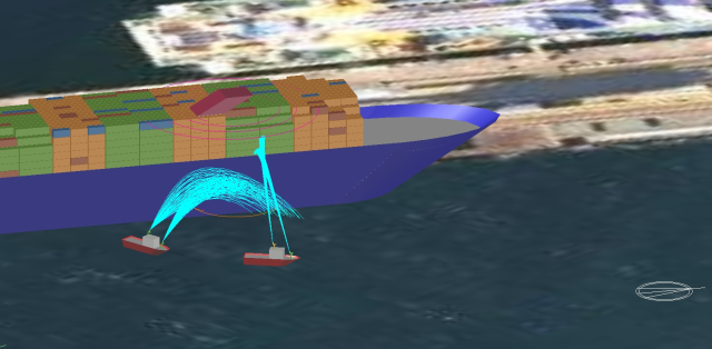
Figure 2-2;water discharge from fire boats to a container ship
|
Example-3
Figure 3-1 shows simulation for water spray system to discharge water to the vertical vessel under wind condition and displayed on 3D AutoCAD drawing. by AutoCAD function of walk through, you can come into the spray to check if dry spot exists.
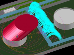
Figure 3-2 shows simulation for water curtain to check the effectiveness for protection of the adjacent tank from a tank fire.
Figure 3-3 shows simulation for water curtain to check the effectiveness for protection of the cooling tower from a tank fire, since the tank is located within 30 m from the cooling tower in contrary to NFPA requirement.
Figure 3-1;spray nozzles 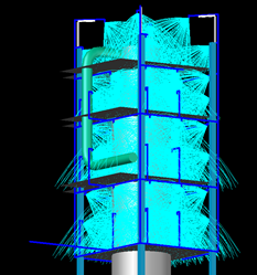 |
Figure 3-2;water curtain between tanks
|
Figure 3-3;protection of cooling tower by water curtain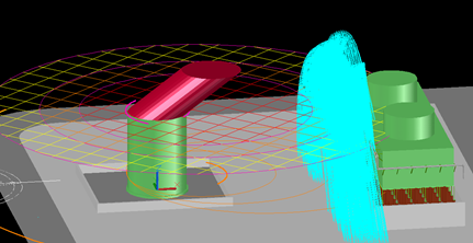 |
Foam Monitor
Foam stream trajectory depends on characteristic on the nozzle type. Based on a nozzle maker's data on discharge trajectory (at least two points are required), specific factors for this software will be decided and then the trajectory simulation will be dedicated for the nozzle.
As described below, this software is applicable for both types of foam nozzle, aspirator type and non- aspirator type.
- Applicable nozzle type
- Aspirator type foam nozzle
air is induced at the inlet of the nozzle and expanded to approx. 7 times in volume, and then foam is discharged from the nozzle.
hand line foam nozzle, foam monitor, foam cannon on the fire truck , telescopic tower foam nozzle etc., - Non-aspirator foam nozzle
Foam solution is discharged from the nozzle and the discharged stream induce the air during flying to expand. Expansion ratio is approx. 2 to 3 times and will be increased with the flying time.
hand line foam nozzle, foam monitor, foam cannon on the fire truck , telescopic tower foam nozzle etc.,
- Aspirator type foam nozzle
- Expansion ratio
In case of aspirator type, expansion ratio will not change during flying through air, but non-aspirator type case, it will be increased with flying time, which is calculated by the program. - Discharge pattern
applicable only for jet stream. - Effect by wind
As well as following wind or against wind, effect of any angle wind can reflect the trajectory simulation. - Foam discharge direction
It is possible to simulate the trajectory for foam discharge in any angle direction. - Display
The trajectory is shown on plant layout or map on 3D AutoCAD drawing.
Example-4
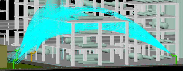
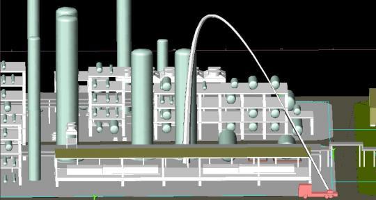
Figure 4-1 shows discharging foam from a telescopic fire truck to a fire beyond the compressor shelter.
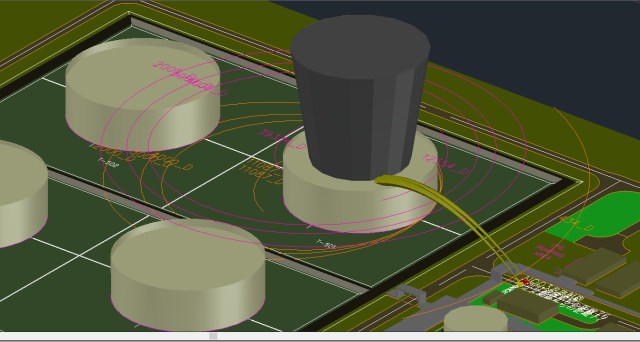
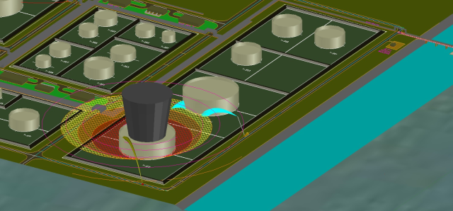
Figure 4-2 shows that foam is discharged from a large foam monitor to a sweet spot of the fired tank. Black column on the tank means zone of higher updraft speed by a fire. Foam will be blown off within the zone.
|
Figure 4-1 foam discharge from fire truck to a fire in process area
|
Figure 4-2 Foam and water discharge from fire truck to a tank fire
|
Example 5
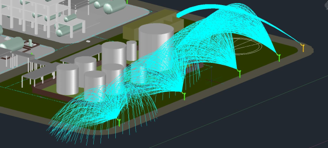
Figure 5-1 shows that foam is discharged from two large foam monitors to the sweet spot of the fired tank beyond the pipe rack. Black column on the tank is the same meaning as the above example.
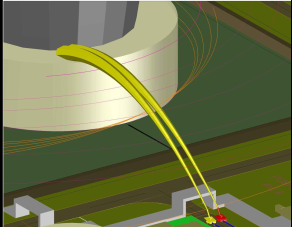
Figure 5-2 is enlarged view around the pipe rack in 3D graphics. For mapping of water or foam discharge equipment, 3D layout graphics are required for confirmation of no obstruction against foam discharge.
|
Figure 5-1 foam discharge from a large foam monitor to a fired tank
|
Figure 5-2 check obstruction for foam discharge
|