VCE/BLEVE/Fireball, Flash Fire
Disasters involved in refineries and chemical plant handling hazardous materials are mainly fire, gas dispersion and explosion. Concerning explosion, there are several kinds of disasters depending on the cause of outbreak as described below. Simulation method is different for each disaster, but our program can deal with everyone.
Our software is based on the disaster prevention guidelines of the petrochemical complex in Japan (hereinafter referred to as “Combi-Guidelines”) and Guidelines for Vapor cloud explosion, pressure vessel burst, BLEVE, and flash fire hazard by American Institute of Chemical Engineers (AIChE).
Please note this program is for explosion in open area (outdoor). Indoor explosion is simulated in numerical calculation.
The software calculates pressure wave from BLEVE or VCE possibly occurring in chemical plants, etc., and diameter, height of the center of fireball following BLEVE with its generated heat radiation. In addition, the possibility of flash fire and the extent of damage are studied by together with gas dispersion simulation.
- VCE (Vapor Cloud Explosion);
Vapor cloud explosion in outdoor, strong pressure wave is generated to damage seriously. - BLEVE (Boiling Liquid Expanding Vapor Explosion);
Rapture of a pressure vessel causes rapid depressurizing and rapid boiling of the liquid to generate pressure wave. - FireBall;
When amount of flammable vapor is discharged into the atmosphere in case of BLEVE etc., and ignited, the vapor is rapidly burned to become burning sphere floating in the air.
Heat radiation from the burning sphere is high intensity to damage to the surrounding facilities and persons. - Flash Fire;
Rapid burning of the flammable gas cloud, but not to generate high pressure wave.
Flammable gas is dispersing and traveling to an ignition source, if the concentration of the gas exceeds LEL (lower explosion limit), then burned rapidly.
Features of flash fire are;- Pressure wave is not generated, so no mechanical damage by the impact.
- Gas concentration is to be within the range of explosion limit. Risk from flash fire is limited to the area of the gas concentration within the explosion limit.
- The risk is being involved in the flame, but not heat radiation. Heat radiation need not be considered since burning time is very short, may be shorter than one second.
It should be noted that, for example, explosion will not occur with no reason, and before explosion, there may be leakage, gas dispersion, and then sometime flash fire, dike fire may occur and result in BLEVE and fireball. That means there may be sequential accidents or disasters before the last disaster.
Pressure wave caused from BLEVE becomes greater in proportion to vapor space in the vessel. Before BLEVE, pressure in the vessel will be increased and then safety relief valve will be activated, and liquid leakage rate will also be increased. So increase of vapor space in the vessel will be accelerated/ These calculation must be reflected to the simulation.
FPEC will do the assessment by various simulation for the sequential disasters from the initial event such as leakage and evaporation, to gas dispersion, fire, and explosion. Please note again, disaster will not occur alone, but multiple accidents or disasters will occur sequentially.
BLEVE
Based on “Combi-Guidelines”, Releasing energy is calculated by either of two formulas below and to calculate equivalent TNT, with which pressure wave reaching distance ranges are calculated.
- Blode formula
- Crowl formula
Flying distance of the broken pieces of the vessel is proportioned to power of amount of liquid which is remains in the vessel at BLEVE, and is calculated by a simplified formula by AIChE.
Please note that BLEVE may occurs for not only flammable liquid, like LPG, but also the vessel storing non flammable liquid, like CO2.
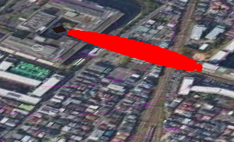
BLEVE Simulation Sample
Case; Propane spherical tank is ruptured following the dike fire
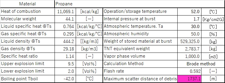
- Figure 1; Table of input data and calculation results
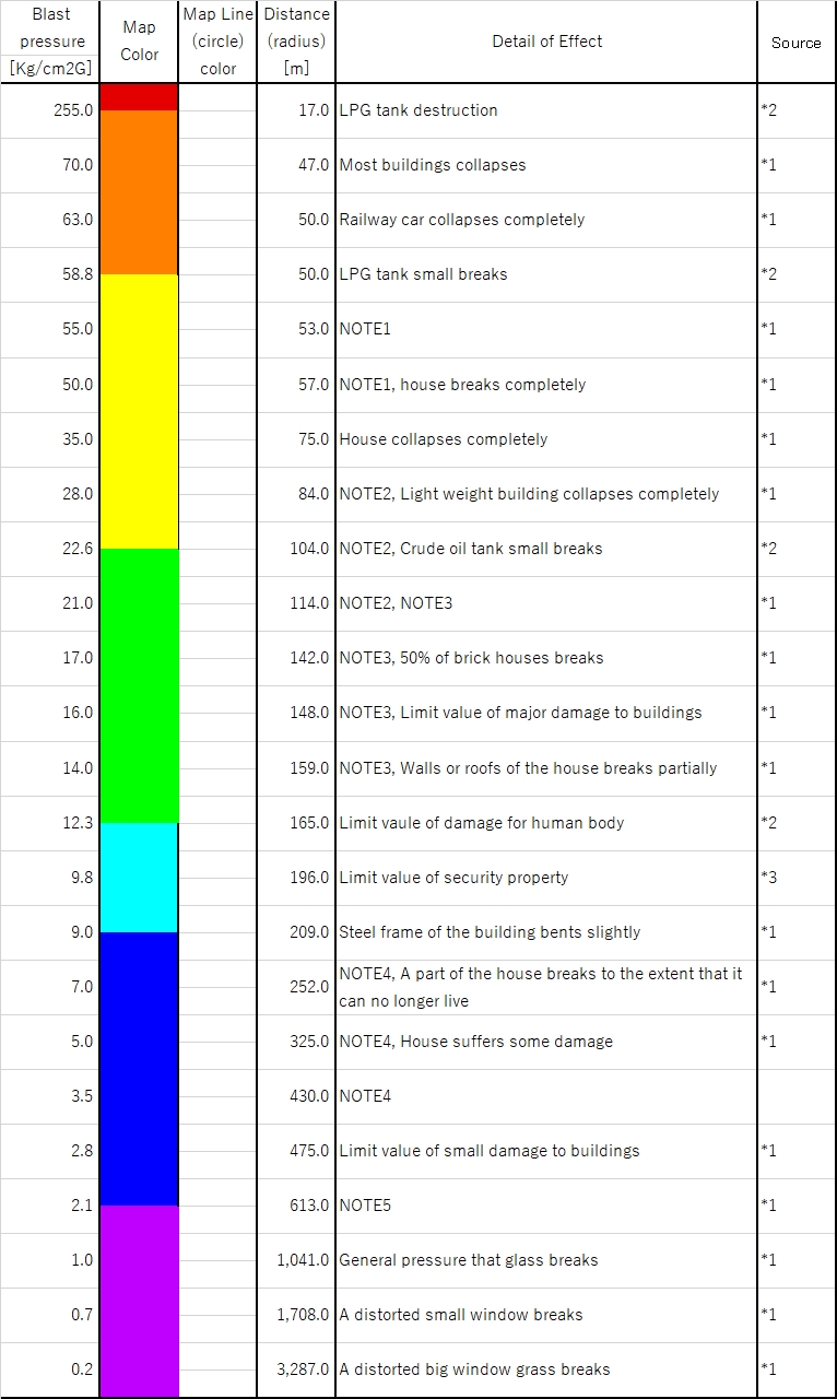
- Figure 2; Table of predetermined pressure wave level by “Combi-Guidelines” and calculated distance.
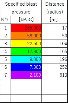
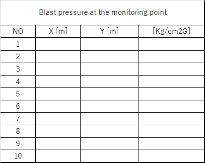
- Figure 3; Table of input pressure wave level and calculated distance
- Figure 4; Table of input distance from the ruptured tank and calculated pressure wave level (in this case, not calculated.)
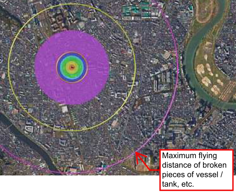
- Picture below is pressure wave map. The colored area is to show the range between two pressure wave level. The circle means radius for a pressure wave reaching. The purple color circle is to show the maximum flying distance of the broken pieces of the vessel.
|
Figure 1
|
Figure 2
|
|
|
Figure 3
|
Figure 4
|
|
FireBall
Based on “Combi-Guidelines”, fireball and its heat radiation are calculated. Diameter, height of the center and life time of the fireball are calculated by either of two methods described below.
The more flammable gas contained in the fireball becomes, the larger fireball becomes. In the program, gas volume contributing fireball is to be 3 times of gas flashed at rupture of the vessel.
- As gas volume contributing fireball, to adopt the sum of the amount of flammable gas and theoretical oxygen (kg)
- Method described in AIChE
Heat radiation is calculated by either of two methods described below.
- To calculate heat flux on the surface faced to the center of the fireball. Calculated heat flux is relatively strong because higher flame temperature of 1750 deg.K is assumed.
- Method described in AIChE. The calculation does not depend on the flame temperature, but depends on physical properties of the flammable gas. And transmittance through air is reflected in the calculation, so when humidity is high and distance is long, heat flux becomes low.
Fireball Simulation Sample
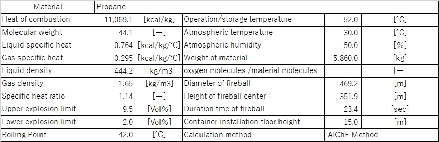
Case; Fireball occurs immediately after BLEVE at Propane spherical tank
- Figure 1; Table of input data and calculation results
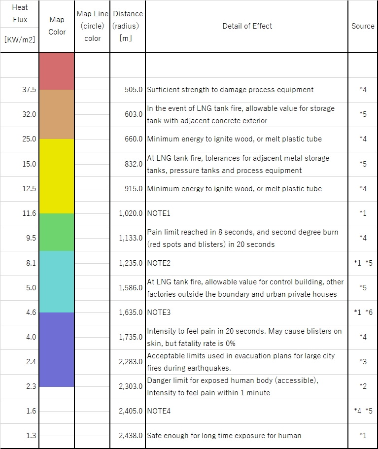
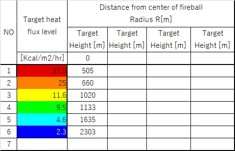
- Figure 2; Table of predetermined heat flux level by “Combi-Guidelines” and calculated distance.
- Figure 3; Table of input heat flux level and calculated distance
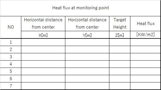
- Figure 4; Table of input distance from the fireball and calculated heat flux level (in this case, not calculated.)
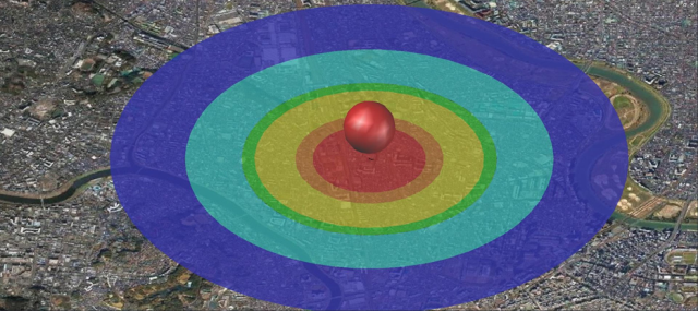
- Picture below is heat flux 3D map. The colored area is to show the range between two heat flux levels. The height and diameter of the fireball is drawn to scale as calculated.
|
Figure 1
|
Figure 2
|
|
|
Figure 3
|
Figure 4
|
|
VCE (Vapor Cloud Explosion)
When an explosion is initiated, surrounding flammable gas is pushed to accelerate the speed when passing a narrow space, and at the result, VCE occurs. So in open space (outdoor) and not congested area, VCE may not occur in general. However, if gas leakage is huge jet yielding strong turbulence, VCE may be possible. It is not easy to simulate VCE, since its severity depends on gas volume and concentration, which may be quite different by ignition time after how long time has passed from initiation of the leakage.
Our program is by TNT equivalency method.
Flash Fire
By our simulation program for gas dispersion, the range in space where gas concentration is over lower explosion limit (LEL) (from safety point of view, we will usually take 50% of LEL) is obtained by the calculation to make 3D gas concentration map. Persons and properties involved in the space may be damaged strongly. Burning time of the flash fire is very short and then fire will go back to the leakage point, which initiate jet fire or diked fire.
Rapid burning of the flammable gas cloud, but not to generate high pressure wave.
Flash Fire Simulation Sample
Case; Propane leaks from the spherical tank and gas dispersed from diked area beyond the boundary line of premises
The space in red color shows the possible flash fire range, which is the space with more than 50%LEL gas concentration.
This 3D map was prepared by AutoCAD, so it is easy to check risk in elevated building.